VkGraphicsPipelineCreateInfo
Building a graphics pipeline is a far more involved task than building a compute pipeline. With the compute pipeline, we only needed a single shader module and pipeline layout, so there was no need of an abstraction layer. But graphics pipelines contain a considerable amount of options, and without a way to simplify it, creating them can be considerably complicated.
For that reason, we will be creating a PipelineBuilder structure, that keeps track of all those options, and will offer some simpler functions to enable/disable features we want, keeping as much defaulted as possible. A lot of those options are things that we wont be using on the tutorial, so trying to reduce the area will be useful.
Some of the options on a pipeline can be set to be dynamic, which means we will set those options when binding the pipeline and recording draw commands. For example we will put viewport as dynamic, as if we had it “baked in”, we would need to create new pipelines if we wanted to change the resolution of our rendering.
Before writing the builder, lets look at what we will need to fill. In the same way creating a compute pipeline required a VkComputePipelineCreateInfo, a graphics one is a VkGraphicsPipelineCreateInfo structure.
typedef struct VkGraphicsPipelineCreateInfo {
    VkStructureType                                  sType;
    const void*                                      pNext;
    VkPipelineCreateFlags                            flags;
    uint32_t                                         stageCount;
    const VkPipelineShaderStageCreateInfo*           pStages;
    const VkPipelineVertexInputStateCreateInfo*      pVertexInputState;
    const VkPipelineInputAssemblyStateCreateInfo*    pInputAssemblyState;
    const VkPipelineTessellationStateCreateInfo*     pTessellationState;
    const VkPipelineViewportStateCreateInfo*         pViewportState;
    const VkPipelineRasterizationStateCreateInfo*    pRasterizationState;
    const VkPipelineMultisampleStateCreateInfo*      pMultisampleState;
    const VkPipelineDepthStencilStateCreateInfo*     pDepthStencilState;
    const VkPipelineColorBlendStateCreateInfo*       pColorBlendState;
    const VkPipelineDynamicStateCreateInfo*          pDynamicState;
    VkPipelineLayout                                 layout;
    VkRenderPass                                     renderPass;
    uint32_t                                         subpass;
    VkPipeline                                       basePipelineHandle;
    int32_t                                          basePipelineIndex;
} VkGraphicsPipelineCreateInfo;
Spec page for graphics pipeline can be found here, which can be used to check things in detail.
stageCount and pStages contains the ShaderStageCreateInfo that will contain the shader modules for the different stages on the pipeline. We will be sending here our fragment shader and vertex shader.
VkPipelineVertexInputStateCreateInfo contains the configuration for vertex attribute input with vertex buffers. If we configure this correctly, our vertex shader will get vertex properties as input in an optimal way. But we will not be using this, as we are just going to send a data array to the shader and index it ourselves, which allows techniques that improve performance and allows more complicated vertex formats that compress data. This is generally known as “vertex pulling”, and even if you are doing equivalent thing as the fixed-hardware vertex input, on modern gpus it will perform about the same.
VkPipelineInputAssemblyStateCreateInfo contains the configuration for triangle topology. We use this to set the pipeline to draw triangles, points, or lines.
VkPipelineTessellationStateCreateInfo is configuration for fixed tesellation. We will not be using this and will leave it as null.
VkPipelineViewportStateCreateInfo contains information about the viewport the pixels will be rendered into. This lets you set what region of pixels will the pipeline draw. We will default it, because we will be using dynamic state for this.
VkPipelineRasterizationStateCreateInfo has the information on how exactly do the triangles get rasterized between the vertex shader and the fragment shader. It has options for depth bias (used when rendering shadows), toggling between wireframe and solid rendering, and the configuration for drawing or skipping backfaces.
VkPipelineMultisampleStateCreateInfo lets us configure Multi Sample antialiasing. Thats a way of improving the antialiasing of our rendering by rasterizing the fragments more times at triangle edges. We will default it to no antialiasing, but we will look into using it later.
VkPipelineDepthStencilStateCreateInfo contains the depth-testing and stencil configuration.
VkPipelineColorBlendStateCreateInfo has the color blending and attachment write information. Its used to make triangles transparent or other blending configurations.
VkPipelineDynamicStateCreateInfo configures dynamic state. One great downside that vulkan pipelines have is that their configuration is “hardcoded” at creation. So if we want to do things like toggle depth-testing on and off, we will need 2 pipelines. It even hardcodes viewport, so if we want to change the size of our render targets, we will also need to rebuild all pipelines. Building pipelines is a very expensive operation, and we want to minimize the number of pipelines used as its critical for performance. For that reason, some of the state of a vulkan pipeline can be set as dynamic, and then the configuration option can be modified at runtime when recording commands. What dynamic state is supported by a given gpu depends on gpu vendor, driver version, and other variables. We will be using dynamic state for our viewport and scissor configuration, as almost all GPUs support that one, and it removes the need to hardcode the draw image resolution when building the pipelines.
The VkGraphicsPipelineCreateInfo takes a VkPipelineLayout that is the same one used when building compute pipelines.
It also takes a VkRenderPass and subpass index. We will not be using that because we use dynamic rendering, so all systems related to VkRenderPass will be completely skipped. Instead, we need to extend the VkGraphicsPipelineCreateInfo with a VkPipelineRenderingCreateInfo added into its pNext chain. This structure holds a list of the attachment formats the pipeline will use.
Lets begin writing the builder. All pipeline code will be on vk_pipelines.h/cpp. You can find it on the shared folder if you are checking the chapter code.
class PipelineBuilder {
public:
    std::vector<VkPipelineShaderStageCreateInfo> _shaderStages;

    VkPipelineInputAssemblyStateCreateInfo _inputAssembly;
    VkPipelineRasterizationStateCreateInfo _rasterizer;
    VkPipelineColorBlendAttachmentState _colorBlendAttachment;
    VkPipelineMultisampleStateCreateInfo _multisampling;
    VkPipelineLayout _pipelineLayout;
    VkPipelineDepthStencilStateCreateInfo _depthStencil;
    VkPipelineRenderingCreateInfo _renderInfo;
    VkFormat _colorAttachmentformat;

	PipelineBuilder(){ clear(); }

    void clear();

    VkPipeline build_pipeline(VkDevice device);
}
The pipeline builder will hold most of the state we need to track of. and an array of color attachment formats and shader stages. The actual CreateInfo structure will be fully filled from the build_pipeline() function. We have a clear() function that will set everything into empty/default properties. The constructor for the pipeline builder will call it, but its useful to have the clear function so we can call it manually when wanted.
Lets write that clear() function first.
void PipelineBuilder::clear()
{
    // clear all of the structs we need back to 0 with their correct stype

    _inputAssembly = { .sType = VK_STRUCTURE_TYPE_PIPELINE_INPUT_ASSEMBLY_STATE_CREATE_INFO };

    _rasterizer = { .sType = VK_STRUCTURE_TYPE_PIPELINE_RASTERIZATION_STATE_CREATE_INFO };

    _colorBlendAttachment = {};

    _multisampling = { .sType = VK_STRUCTURE_TYPE_PIPELINE_MULTISAMPLE_STATE_CREATE_INFO };

    _pipelineLayout = {};

    _depthStencil = { .sType = VK_STRUCTURE_TYPE_PIPELINE_DEPTH_STENCIL_STATE_CREATE_INFO };

    _renderInfo = { .sType = VK_STRUCTURE_TYPE_PIPELINE_RENDERING_CREATE_INFO };

    _shaderStages.clear();
}
We will set the .sType of every structure here, and leave everything else as 0. This is using cpp20 initializers, so the parameters we dont write from within the brackets will be defaulted to 0. Most of the Info structures in vulkan are designed so that 0 is valid clear/default option, so this works great here.
Lets begin writing the build_pipeline function. first we will begin by setting some of the Info structures we are missing because they wont be configured.
VkPipeline PipelineBuilder::build_pipeline(VkDevice device)
{
    // make viewport state from our stored viewport and scissor.
    // at the moment we wont support multiple viewports or scissors
    VkPipelineViewportStateCreateInfo viewportState = {};
    viewportState.sType = VK_STRUCTURE_TYPE_PIPELINE_VIEWPORT_STATE_CREATE_INFO;
    viewportState.pNext = nullptr;

    viewportState.viewportCount = 1;
    viewportState.scissorCount = 1;

    // setup dummy color blending. We arent using transparent objects yet
    // the blending is just "no blend", but we do write to the color attachment
    VkPipelineColorBlendStateCreateInfo colorBlending = {};
    colorBlending.sType = VK_STRUCTURE_TYPE_PIPELINE_COLOR_BLEND_STATE_CREATE_INFO;
    colorBlending.pNext = nullptr;

    colorBlending.logicOpEnable = VK_FALSE;
    colorBlending.logicOp = VK_LOGIC_OP_COPY;
    colorBlending.attachmentCount = 1;
    colorBlending.pAttachments = &_colorBlendAttachment;

    // completely clear VertexInputStateCreateInfo, as we have no need for it
    VkPipelineVertexInputStateCreateInfo _vertexInputInfo = { .sType = VK_STRUCTURE_TYPE_PIPELINE_VERTEX_INPUT_STATE_CREATE_INFO };
We first fill VkPipelineViewportStateCreateInfo with just viewport count and nothing else. With dynamic viewport state we dont need to fill the viewport or stencil options here.
Then we fill VkPipelineColorBlendStateCreateInfo with some default options for logic blending (we wont use it), and hook the VkPipelineColorBlendAttachmentState for the blending options for a single attachment. We only support rendering to one attachment here, so this is fine. It can be made into an array of VkPipelineColorBlendAttachmentState if drawing to multiple attachments is needed.
Lets continue with the function, and begin filling the VkGraphicsPipelineCreateInfo
    // build the actual pipeline
    // we now use all of the info structs we have been writing into into this one
    // to create the pipeline
    VkGraphicsPipelineCreateInfo pipelineInfo = { .sType = VK_STRUCTURE_TYPE_GRAPHICS_PIPELINE_CREATE_INFO };
    // connect the renderInfo to the pNext extension mechanism
    pipelineInfo.pNext = &_renderInfo;

    pipelineInfo.stageCount = (uint32_t)_shaderStages.size();
    pipelineInfo.pStages = _shaderStages.data();
    pipelineInfo.pVertexInputState = &_vertexInputInfo;
    pipelineInfo.pInputAssemblyState = &_inputAssembly;
    pipelineInfo.pViewportState = &viewportState;
    pipelineInfo.pRasterizationState = &_rasterizer;
    pipelineInfo.pMultisampleState = &_multisampling;
    pipelineInfo.pColorBlendState = &colorBlending;
    pipelineInfo.pDepthStencilState = &_depthStencil;
    pipelineInfo.layout = _pipelineLayout;
We connect all of the configuration structures we have on the builder, and add _renderInfo into the pNext of the graphics pipeline info itself.
next is setting up dynamic state
    VkDynamicState state[] = { VK_DYNAMIC_STATE_VIEWPORT, VK_DYNAMIC_STATE_SCISSOR };

    VkPipelineDynamicStateCreateInfo dynamicInfo = { .sType = VK_STRUCTURE_TYPE_PIPELINE_DYNAMIC_STATE_CREATE_INFO };
    dynamicInfo.pDynamicStates = &state[0];
    dynamicInfo.dynamicStateCount = 2;

    pipelineInfo.pDynamicState = &dynamicInfo;
Setting up dynamic state is just filling a VkPipelineDynamicStateCreateInfo with an array of VkDynamicState enums. We will use these 2 for now.
This is all we needed for the pipeline, so we can finally call the create function.
    // its easy to error out on create graphics pipeline, so we handle it a bit
    // better than the common VK_CHECK case
    VkPipeline newPipeline;
    if (vkCreateGraphicsPipelines(device, VK_NULL_HANDLE, 1, &pipelineInfo,
            nullptr, &newPipeline)
        != VK_SUCCESS) {
        fmt::println("failed to create pipeline");
        return VK_NULL_HANDLE; // failed to create graphics pipeline
    } else {
        return newPipeline;
    }
And thats it with the main creation function. We now need to actually set the options properly, as right now the entire pipeline is essentially null, which will error as-is due to missing options.
void PipelineBuilder::set_shaders(VkShaderModule vertexShader, VkShaderModule fragmentShader)
{
    _shaderStages.clear();

    _shaderStages.push_back(
        vkinit::pipeline_shader_stage_create_info(VK_SHADER_STAGE_VERTEX_BIT, vertexShader));

    _shaderStages.push_back(
        vkinit::pipeline_shader_stage_create_info(VK_SHADER_STAGE_FRAGMENT_BIT, fragmentShader));
}
We begin by adding a function to set the vertex and fragment shaders. We add them into the _shaderStages array with the proper info creation, which we already had from building the compute pipeline.
Next we add a function to set input topology
void PipelineBuilder::set_input_topology(VkPrimitiveTopology topology)
{
    _inputAssembly.topology = topology;
    // we are not going to use primitive restart on the entire tutorial so leave
    // it on false
    _inputAssembly.primitiveRestartEnable = VK_FALSE;
}
VkPrimitiveTopology has the options for VK_PRIMITIVE_TOPOLOGY_TRIANGLE_LIST, VK_PRIMITIVE_TOPOLOGY_POINT_LIST, and so on. PrimitiveRestart is used for triangle strips and line strips, but we dont use it.
The rasterizer state is a big one so we will split it on a few options.
void PipelineBuilder::set_polygon_mode(VkPolygonMode mode)
{
    _rasterizer.polygonMode = mode;
    _rasterizer.lineWidth = 1.f;
}
We need to have lineWidth as 1.f as default, then we set the polygon mode, which controls wireframe vs solid rendering and point rendering.
void PipelineBuilder::set_cull_mode(VkCullModeFlags cullMode, VkFrontFace frontFace)
{
    _rasterizer.cullMode = cullMode;
    _rasterizer.frontFace = frontFace;
}
Cull mode will set the front face and the cull mode for backface culling.
Next is setting the multisample state. We will default the structure to multisampling disabled. Later we can add other functions for enabling different multisampling levels for antialiasing
void PipelineBuilder::set_multisampling_none()
{
    _multisampling.sampleShadingEnable = VK_FALSE;
    // multisampling defaulted to no multisampling (1 sample per pixel)
    _multisampling.rasterizationSamples = VK_SAMPLE_COUNT_1_BIT;
    _multisampling.minSampleShading = 1.0f;
    _multisampling.pSampleMask = nullptr;
    // no alpha to coverage either
    _multisampling.alphaToCoverageEnable = VK_FALSE;
    _multisampling.alphaToOneEnable = VK_FALSE;
}
Next we will add a function for blending mode
void PipelineBuilder::disable_blending()
{
    // default write mask
    _colorBlendAttachment.colorWriteMask = VK_COLOR_COMPONENT_R_BIT | VK_COLOR_COMPONENT_G_BIT | VK_COLOR_COMPONENT_B_BIT | VK_COLOR_COMPONENT_A_BIT;
    // no blending
    _colorBlendAttachment.blendEnable = VK_FALSE;
}
We will have our disable_blending() function that sets blendEnable to false but sets the correct write mask. We will add functions for more blending modes later. We need to setup a proper colorWriteMask here so that our pixel output will write to the attachment correctly.
Now we hook our formats, lets add the functions for both depth testing and color attachment.
void PipelineBuilder::set_color_attachment_format(VkFormat format)
{
    _colorAttachmentformat = format;
    // connect the format to the renderInfo  structure
    _renderInfo.colorAttachmentCount = 1;
    _renderInfo.pColorAttachmentFormats = &_colorAttachmentformat;
}

void PipelineBuilder::set_depth_format(VkFormat format)
{
    _renderInfo.depthAttachmentFormat = format;
}
On the color attachment, the pipeline needs it by pointer because it wants an array of color attachments. This is useful for things like deferred rendering where you draw to multiple images at once, but we dont need this yet so we can default it to just 1 color format.
The last one we need is a function to disable the depth testing logic.
void PipelineBuilder::disable_depthtest()
{
    _depthStencil.depthTestEnable = VK_FALSE;
    _depthStencil.depthWriteEnable = VK_FALSE;
    _depthStencil.depthCompareOp = VK_COMPARE_OP_NEVER;
    _depthStencil.depthBoundsTestEnable = VK_FALSE;
    _depthStencil.stencilTestEnable = VK_FALSE;
    _depthStencil.front = {};
    _depthStencil.back = {};
    _depthStencil.minDepthBounds = 0.f;
    _depthStencil.maxDepthBounds = 1.f;
}
With all the basic features for the pipeline builder filled, we can now draw a triangle. For our triangle, we are going to use hardcoded vertex positions in the vertex shader, and the output will be a pure color.
These are the shaders:
colored_triangle.vert
#version 450

layout (location = 0) out vec3 outColor;

void main()
{
	//const array of positions for the triangle
	const vec3 positions[3] = vec3[3](
		vec3(1.f,1.f, 0.0f),
		vec3(-1.f,1.f, 0.0f),
		vec3(0.f,-1.f, 0.0f)
	);

	//const array of colors for the triangle
	const vec3 colors[3] = vec3[3](
		vec3(1.0f, 0.0f, 0.0f), //red
		vec3(0.0f, 1.0f, 0.0f), //green
		vec3(00.f, 0.0f, 1.0f)  //blue
	);

	//output the position of each vertex
	gl_Position = vec4(positions[gl_VertexIndex], 1.0f);
	outColor = colors[gl_VertexIndex];
}
colored_triangle.frag
#version 450

//shader input
layout (location = 0) in vec3 inColor;

//output write
layout (location = 0) out vec4 outFragColor;

void main()
{
	//return red
	outFragColor = vec4(inColor,1.0f);
}
In our vertex shader, we have a hardcoded array of positions, and we index into it from gl_VertexIndex. This works in a similar way to LocalThreadID on compute shaders worked. For every invocation of the vertex shader, this will be a different index, and we can use it to process out vertex, which will write into the fixed function gl_Position variable. As the array is only of lenght 3, if we tried to render more than 3 vertices (1 triangle) this will error.
In our fragment shader, we will declare an output at layout = 0 (this connects to the render attachments of the render pass), and we have a simple hardcoded red output.
Lets now create the pipeline and layout we need to draw this triangle. We are adding new shader files, so make sure you rebuild the CMake project and build the Shaders target.
On VulkanEngine class, we will add a init_triangle_pipeline() function, and a couple of members to hold the pipeline and its layout
VkPipelineLayout _trianglePipelineLayout;
VkPipeline _trianglePipeline;

void init_triangle_pipeline();
We will call this init_triangle_pipeline() from init_pipelines() function.
Lets write that function We will start by loading the 2 shaders into VkShaderModules, like we did with the compute shader, but this time more shaders.
	VkShaderModule triangleFragShader;
	if (!vkutil::load_shader_module("../../shaders/colored_triangle.frag.spv", _device, &triangleFragShader)) {
		fmt::print("Error when building the triangle fragment shader module");
	}
	else {
		fmt::print("Triangle fragment shader succesfully loaded");
	}

	VkShaderModule triangleVertexShader;
	if (!vkutil::load_shader_module("../../shaders/colored_triangle.vert.spv", _device, &triangleVertexShader)) {
		fmt::print("Error when building the triangle vertex shader module");
	}
	else {
		fmt::print("Triangle vertex shader succesfully loaded");
	}

	//build the pipeline layout that controls the inputs/outputs of the shader
	//we are not using descriptor sets or other systems yet, so no need to use anything other than empty default
	VkPipelineLayoutCreateInfo pipeline_layout_info = vkinit::pipeline_layout_create_info();
	VK_CHECK(vkCreatePipelineLayout(_device, &pipeline_layout_info, nullptr, &_trianglePipelineLayout));
We also create the pipeline layout. Unlike with the compute shader before, this time we have no push constants and no descriptor bindings on here, so its really just a completely empty layout.
Now we create the pipeline, using the Pipeline Builder created before.
	PipelineBuilder pipelineBuilder;

	//use the triangle layout we created
	pipelineBuilder._pipelineLayout = _trianglePipelineLayout;
	//connecting the vertex and pixel shaders to the pipeline
	pipelineBuilder.set_shaders(triangleVertexShader, triangleFragShader);
	//it will draw triangles
	pipelineBuilder.set_input_topology(VK_PRIMITIVE_TOPOLOGY_TRIANGLE_LIST);
	//filled triangles
	pipelineBuilder.set_polygon_mode(VK_POLYGON_MODE_FILL);
	//no backface culling
	pipelineBuilder.set_cull_mode(VK_CULL_MODE_NONE, VK_FRONT_FACE_CLOCKWISE);
	//no multisampling
	pipelineBuilder.set_multisampling_none();
	//no blending
	pipelineBuilder.disable_blending();
	//no depth testing
	pipelineBuilder.disable_depthtest();

	//connect the image format we will draw into, from draw image
	pipelineBuilder.set_color_attachment_format(_drawImage.imageFormat);
	pipelineBuilder.set_depth_format(VK_FORMAT_UNDEFINED);

	//finally build the pipeline
	_trianglePipeline = pipelineBuilder.build_pipeline(_device);

	//clean structures
	vkDestroyShaderModule(_device, triangleFragShader, nullptr);
	vkDestroyShaderModule(_device, triangleVertexShader, nullptr);

	_mainDeletionQueue.push_function([&]() {
		vkDestroyPipelineLayout(_device, _trianglePipelineLayout, nullptr);
		vkDestroyPipeline(_device, _trianglePipeline, nullptr);
	});
With the pipeline built, we can draw our triangle as part of the command buffer we create every frame.
The compute shader we run for the background needed to draw into GENERAL image layout, but when doing geometry rendering, we need to use COLOR_ATTACHMENT_OPTIMAL. It is possible to draw into GENERAL layout with graphics pipelines, but its lower performance and the validation layers will complain. We will create a new function, draw_geometry(), to hold these graphics commands. Lets update the draw loop first.
	VK_CHECK(vkBeginCommandBuffer(cmd, &cmdBeginInfo));

	// transition our main draw image into general layout so we can write into it
	// we will overwrite it all so we dont care about what was the older layout
	vkutil::transition_image(cmd, _drawImage.image, VK_IMAGE_LAYOUT_UNDEFINED, VK_IMAGE_LAYOUT_GENERAL);

	draw_background(cmd);

	vkutil::transition_image(cmd, _drawImage.image, VK_IMAGE_LAYOUT_GENERAL, VK_IMAGE_LAYOUT_COLOR_ATTACHMENT_OPTIMAL);

	draw_geometry(cmd);

	//transtion the draw image and the swapchain image into their correct transfer layouts
	vkutil::transition_image(cmd, _drawImage.image, VK_IMAGE_LAYOUT_COLOR_ATTACHMENT_OPTIMAL, VK_IMAGE_LAYOUT_TRANSFER_SRC_OPTIMAL);
	vkutil::transition_image(cmd, _swapchainImages[swapchainImageIndex], VK_IMAGE_LAYOUT_UNDEFINED, VK_IMAGE_LAYOUT_TRANSFER_DST_OPTIMAL);
Now fill the draw_geometry function
void VulkanEngine::draw_geometry(VkCommandBuffer cmd)
{
	//begin a render pass  connected to our draw image
	VkRenderingAttachmentInfo colorAttachment = vkinit::attachment_info(_drawImage.imageView, nullptr, VK_IMAGE_LAYOUT_COLOR_ATTACHMENT_OPTIMAL);

	VkRenderingInfo renderInfo = vkinit::rendering_info(_drawExtent, &colorAttachment, nullptr);
	vkCmdBeginRendering(cmd, &renderInfo);

	vkCmdBindPipeline(cmd, VK_PIPELINE_BIND_POINT_GRAPHICS, _trianglePipeline);

	//set dynamic viewport and scissor
	VkViewport viewport = {};
	viewport.x = 0;
	viewport.y = 0;
	viewport.width = _drawExtent.width;
	viewport.height = _drawExtent.height;
	viewport.minDepth = 0.f;
	viewport.maxDepth = 1.f;

	vkCmdSetViewport(cmd, 0, 1, &viewport);

	VkRect2D scissor = {};
	scissor.offset.x = 0;
	scissor.offset.y = 0;
	scissor.extent.width = _drawExtent.width;
	scissor.extent.height = _drawExtent.height;

	vkCmdSetScissor(cmd, 0, 1, &scissor);

	//launch a draw command to draw 3 vertices
	vkCmdDraw(cmd, 3, 1, 0, 0);

	vkCmdEndRendering(cmd);
}
To draw our triangle we need to begin a renderpass with cmdBeginRendering. This is the same we were doing for imgui last chapter, but this time we are pointing it into our _drawImage instead of the swapchain image.
We do a CmdBindPipeline, but instead of using the BIND_POINT_COMPUTE, we now use VK_PIPELINE_BIND_POINT_GRAPHICS. Then, we have to set our viewport and scissor. This is required before we left them undefined when creating the pipeline as we were using dynamic pipeline state. With that set, we can do a vkCmdDraw() to draw the triangle. With that done, we can finish the render pass to end our drawing.
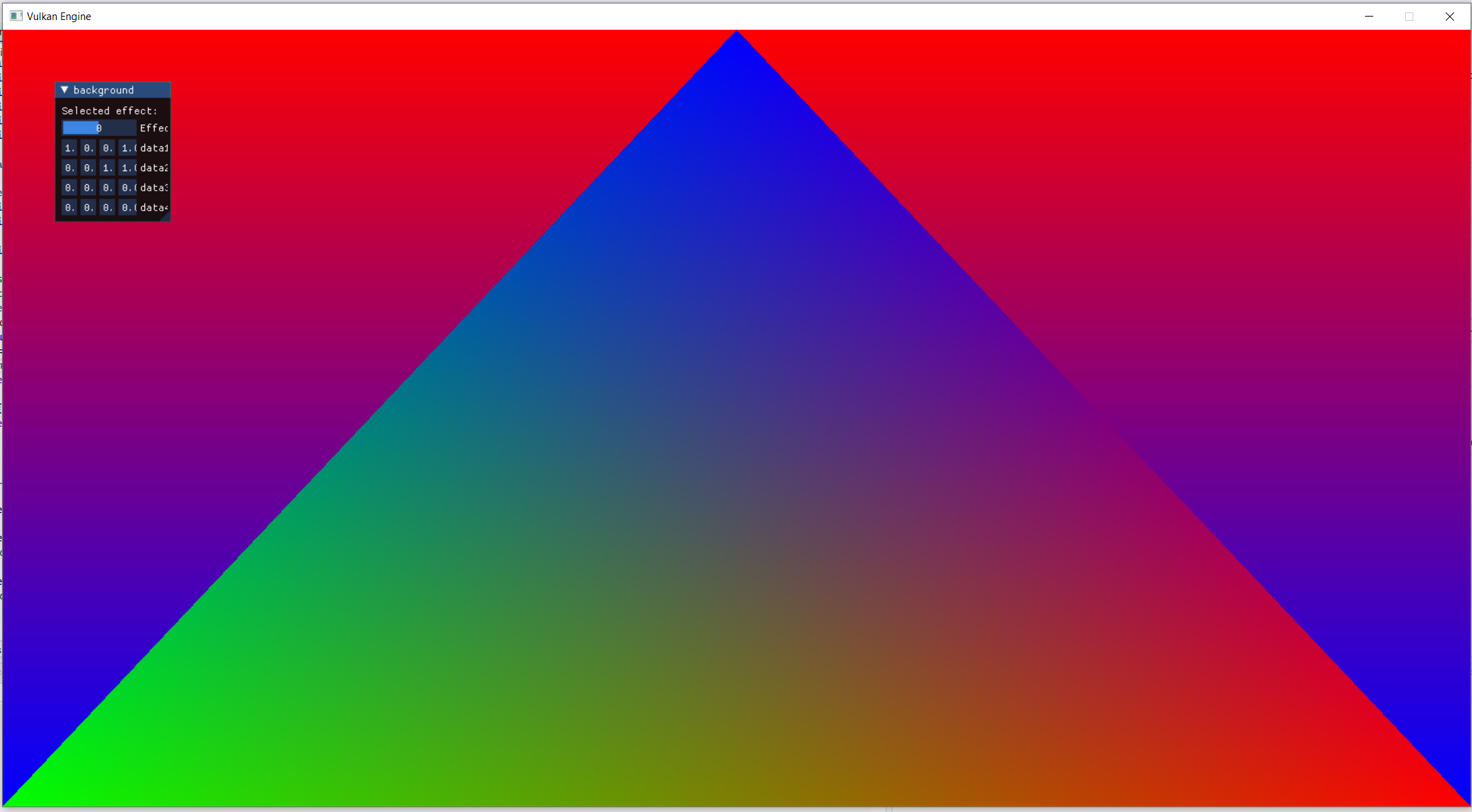
If you run the program at this point, you should see a triangle being rendered on top of the compute based background
Next: Mesh buffers