The core of all voxel engines is determining what technique to use for drawing them. Are your voxels all pure-color cubes? Maybe it’s a Minecraft-like engine where there are more objects than cubes? In Project Ascendant, I took the techniques from the Minecraft mod NoCubes. This mod hijacks the Minecraft mesh generation and applies a smoothing step on the ground blocks. There are multiple techniques to use for the smoothing, but the one I implemented is based on the SurfaceNets algorithm, which works by generating your typical cube-based geometry, and then smoothing the vertices depending on the 8 blocks around each vertex. This works great, but it means we are no longer on a grid, which prevents some optimizations. Even so, I still implemented a pure-cubes voxel renderer to use for the far draws, so the engine has 5 different geometry draw systems.
- Voxel-mesh rendering: Heavily quantized to compress the data, these are the near field meshes for the world geometry.
- Voxel-raycast Fardraws: Storing individual blocks, drawing each block as a sprite, and then raycasting the block within the sprite. Limited to block-only rendering, but very high performance so it’s used for the far distance drawing.
- Voxel-raycast Fardraws (with quads instead): Storing individual blocks, drawing each block as 3 camera-facing quads.
- Vegetation clutter: Instanced drawing system with vertex animation, for all the grass.
- Arbitrary mesh rendering (allows animation): For enemies, props, and all sorts of things where they are loaded from a GLTF and aren’t voxels
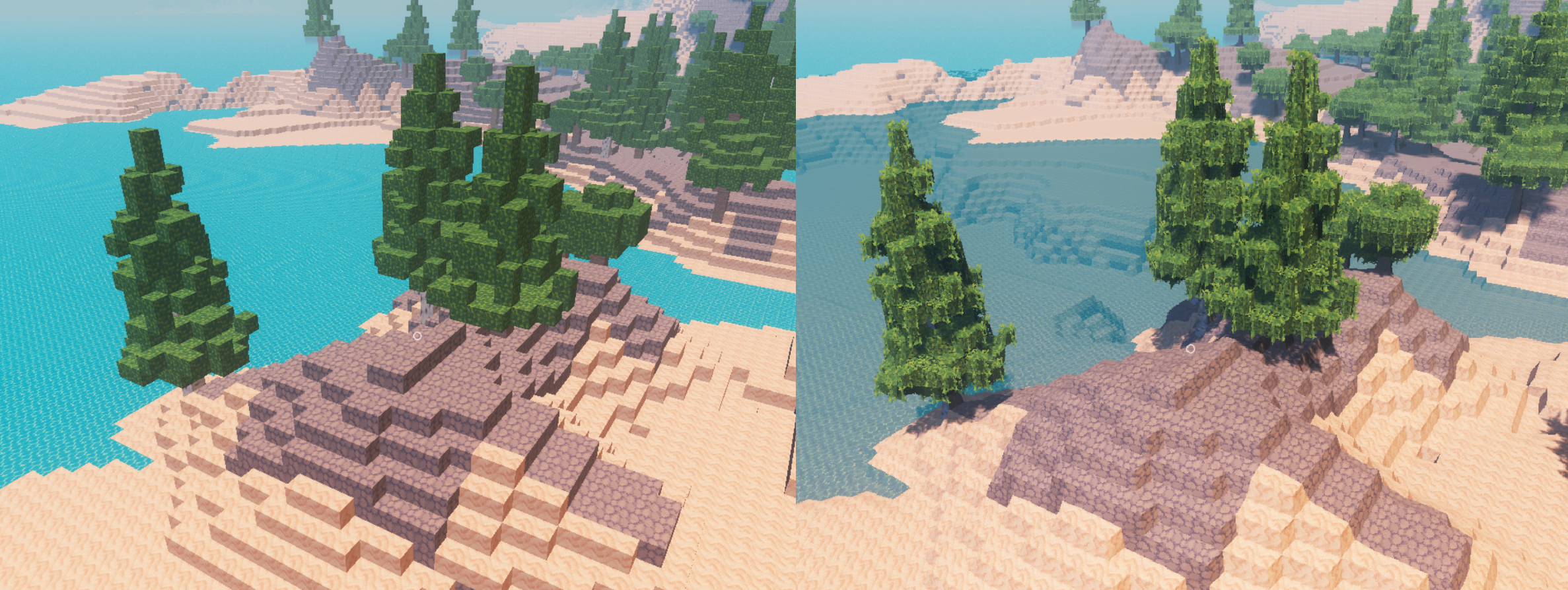
In this image you can see the difference between the blocky draws that are used for distance rendering and the smoothed detail meshes used close
As there are 5 different rendering systems with different properties, I decided to move the engine to a deferred rendering scheme. That way I only need to care about writing the gbuffer, and the lighting math is unified when the deferred light is applied later in the frame.
In voxel engines and Minecraft-likes, there are 2 main bottlenecks to the rendering performance (in regards to GPU, at least). The first is memory usage for the generated meshes and/or voxels, and the second is geometry density. As voxels are 3-dimensional and scale as O(n³) when you increase the draw distance, you will fill your RAM very, very quickly. Even with culling, you still need to generate those voxel meshes so that they are ready to be drawn.
Compressing your buffers on the GPU is of the utmost importance, and makes a huge difference. Your shaders for geometry will be quite simple, especially on a deferred engine, so the rendering will be completely memory bottlenecked, other than just having too many triangles to draw. This is the main reason for Minecraft to use so much VRAM when the draw distance grows.
The amount of triangles that voxel engines can throw at the screen is quite high once the draw distance increases. You quickly get into 1 pixel = 1 voxel or even lower, and your options are to either implement some sort of Level of Detail so that distance zones have bigger voxels, or you switch to a faster rendering technique. The Minecraft Distant Horizons mod does both, and you can see it increasing the voxel size as the distance grows. With so many triangles, you want to have a simple pixel shader so that quad invocations don’t decrease your performance under these constraints, which is why voxel engines work quite well with deferred or visibility buffer approaches.
Architecture for voxel draws
In Ascendant, I decided to go for a chunk size of 8x8x8 voxels across the entire engine. For reference, Minecraft uses 16x256x16, with them moving to have sub-chunks that are more like 16x16x16 in modern versions. Vintage Story uses a 32x32x32 voxel chunk size. A given chunk will be 1 “unit” of mesh generation, and 1 mesh to draw. Chunks can also have multiple “layers” to them, for example water rendering vs ground rendering, that render at different passes.
The main tradeoff of chunk size is that the bigger your chunks, the fewer draws you have, but also your draws become bigger so they cull worse. There isn’t really an optimal chunk size, as it’s something that changes the design of the engine and heavily depends on the data.
The 3 voxel-draws + the vegetation system work through the same system, as part of the BlockRenderer class. This design works by having a very big buffer that is allocated at engine startup (I use 400 megabytes) - I’ll call this buffer “gigabuffer” - and then the buffers for their data get sub-allocated on there thanks to VMA Virtual Allocation feature. This could use buffer device address, but I suballocate like this so that it’s unified into 1 buffer for transfer operations and so I can use 32-bit offsets into the buffer instead of 64-bit pointers.

In the renderer, there are 2 big arrays of chunk information that get uploaded to the GPU too. The first one contains the “near field” chunks, and the second the far field.
As its simpler, lets begin with the far field system.
struct ChunkDrawInfo {
    glm::ivec3 position;
    int16_t type;
    int16_t drawcount; // number of blocks it draws. if value is -1 it needs data refresh
    int32_t index; // index into gigabuffer  if value is -1 its not allocated on gigabuffer
};
A chunk definition is just a position + type, drawcount, and the index into the gigabuffer. Its position is in block-coordinates, integer. So I can put chunks at any position I wish within int32 boundary.
The type is used to separate between the quad-draw system and the far field sprite raycaster. The drawcount contains how many things this chunk has; it can be either quads or voxels.
The data it allocates on the gigabuffer can be an array of these
struct DrawBlock {
    // uint32_t drawflags: 4;
    // uint32_t pos : 12; //packed 4 bits each chunk-local
    // uint32_t type : 16;

    uint32_t packed;
}
A Block that is a 32-bit packed version of a blockID + its position and a couple flags. Only visible blocks are put into the data, so blocks below the ground will not be contained there. Only surface blocks do. So for example, in a flat field, an 8x8x8 chunk will contain 8x8 = 64 block data entries as there is only 1 layer visible. As the chunks are all 8x8x8, with 4 bits per axis I can cover the possible positions for that block. With 4 bits I could also make it go into 16x16x16 chunks as it fits there too.
The voxel renderer does not take care of generating these lists. It only draws and manages the gpu side memory. Its relevant api is just this
    ChunkDrawID UploadNewChunk(glm::ivec3 chunkPos, DrawBlock* blocks, int count);

    void FreeChunkDraw(ChunkDrawID id);
    bool IsHandleValid(ChunkDrawID id);
When uploading new block lists for the chunks, it writes the block data into a CPU-side staging buffer, and then at the start of the frame it does a compute shader that copies the data into the gigabuffer on the GPU side. Updating chunks is not supported; you just create a new chunk and delete the old one.
There are 2 strategies for rendering these lists of blocks: one is the sprite renderer, and the other is drawing 3 quads per block. The sprite renderer is faster, but on machines with low compute power, the 3-quad renderer goes faster at lower distance. The BlockID information is also uploaded to the GPU so that the shaders know what textures to use per BlockID.
The sprite renderer is based on this paper: A Ray-Box Intersection Algorithm and Efficient Dynamic Voxel Rendering.
The idea is that we do one quad (or point) per voxel, and in the pixel shader, we perform a ray/box intersection to calculate the exact collision. This lets us draw a box (or other shape!) with only a single quad or point draw. The downside of it is that we need to do tricks with outputting depth from the pixel shader, which must be used carefully. As it’s raytracing geometry inside the pixel shader, it can’t be used with MSAA. In the paper, they recommend drawing as points or using a geometry shader to augment a point into a quad. I decided to do a fairly common particle system trick to draw quads.
In this screenshot I have removed the discard logic that removes pixel outside of the rendered sprites, which clearly shows how each cube is a quad sprite. ![]()
The other renderer just finds the global voxel position, and moves 3 quads to face the camera to match the 3 visible sides of the cube. It got removed once I added the smooth mesh system and left the other for the far distance draws.
The chunks are drawn with indirect drawing, so that the culling is done on the GPU. In the Ascendant screenshots shown, there can be up to around 400,000 chunks, so culling on CPU for such a high number is a non-starter.
The engine does not implement pyramid-based depth culling as shown here, but it could use it no problem. I just didn’t find need to add that in practice as it’s more useful if there are cave networks but I don’t have those and performance was already high.
First, the engine has to sync the memory of the ChunkDrawInfo array to the GPU. This is done by directly writing the chunk draw info array into a CPU-side buffer. This could be done with a scatter upload step like the blocks use, but it was fast enough so it was preferable to avoid the complexity of handling that.
Every time the chunks need to be drawn, I run a compute shader that outputs into an indirect buffer + indirect count. Shadow passes and main view passes reuse the same indirect buffer. The cull shader looks like this:
struct ChunkDrawIndirect {
    //draw indirect params
    uint32_t indexCount;
    uint32_t instanceCount;
    uint32_t firstIndex;
    int32_t vertexOffset;
    uint32_t firstInstance;

    //chunk x/y/z pos
    int32_t chunkx;
    int32_t chunky;
    int32_t chunkz;
}

[shader("compute")]
[numthreads(256, 1, 1)]
void mainPassCull(

    [[vk::binding(0, 0)]] StructuredBuffer<CullInputData> sceneData,
    [[vk::binding(1, 0)]] RWStructuredBuffer<ChunkDrawIndirect> drawCommands,
    [[vk::binding(2, 0)]] StructuredBuffer<ChunkDrawInfo> chunkInfo,
    [[vk::binding(3, 0)]] RWStructuredBuffer<uint32_t> drawCount,

    uint3 threadId: SV_DispatchThreadID)
{

    uint idx = threadId.x;
    if (idx < sceneData[0].chunkCount && chunkInfo[idx].drawcount > 0) {
        if (IsVisible(chunkInfo[idx], sceneData[0])) {

            uint drawIdx = atomicAdd(drawCount[0], 1);

            drawCommands[drawIdx].chunkx = chunkInfo[idx].position_x;
            drawCommands[drawIdx].chunky = chunkInfo[idx].position_y;
            drawCommands[drawIdx].chunkz = chunkInfo[idx].position_z;
            drawCommands[drawIdx].firstIndex = 0;
            drawCommands[drawIdx].firstInstance = drawIdx;
            drawCommands[drawIdx].instanceCount = 1;

            //2 tris worth. to draw a quad
            drawCommands[drawIdx].indexCount = chunkInfo[idx].drawcount * 6;
            drawCommands[drawIdx].vertexOffset = int32_t(chunkInfo[idx].index) * 4;

        }
    }
}
This is pretty much the simplest possible type of draw indirect system. One chunk = 1 draw-indirect command, storing the chunk location in the command too. I use vertex offset to offset where in the gigabuffer the data is being loaded from. Each chunk has different data, so it doesn’t make sense to use instanced draws here. sceneData contains an array of culling planes to use, which changes depending on whether it’s the main view or a shadow cull step.
In the vertex shader, I calculate the bounding box in screenspace of the block we are trying to draw, by transforming its 8 corner points into screenspace. From that, I output the 4 vertices of the quad.
In the pixel shader, it finds the camera ray from the pixel position, and then raycasts the ray vs the block we want to render. After that, it outputs the texture color according to blockID.
There are a few inefficiencies in this system in the way it’s implemented, but it’s still fast enough to draw voxel counts into the millions. The obvious move forward is to perform culling on an individual block basis, by making it output individual blocks into an array instead of doing indirect per chunk. Similar to techniques like Nanite, but done on a per-block basis. Using mesh shaders for this would also improve the performance nicely by simplifying the shaders that output quads.
Voxel Meshed Draws
With that system for pure cubes explained, we can now move forward to the meshed draws. At the core, it works mostly the same. The difference is that the meshed draws have multiple “draws” for 1 chunk to support transparent draws and vegetation, and the format for the vertices is different, as now we are dealing with normal meshes, not fixed blocks.
The system does not generate index buffers. Instead, all of the mesh generation outputs quads. But these quads are quads with arbitrary 4 points, they aren’t like the cubes where they are flat quads. By restricting the topology of the mesh to quads, we can simplify the data management as we don’t need to care about index buffers for the draw indirect logic, and it now relies on reusing the same quad index buffer for everything.
The vertex format is this.
//compact packed vertex for environment/block generators
struct BlockVertex {
    //unorm position because block generators are well bounded
    uint16_t position_x{ 0 };
    uint16_t position_y{ 0 };
    uint16_t position_z{ 0 };

    //low precision octahedral is fine
    uint16_t encodedNormal{ 0 }; // octahedral 8b

    //unorm uv
    uint16_t uv_x{ 0 };
    uint16_t uv_y{ 0 };

    //extra
    uint16_t blockID{ 0 };
    uint16_t extra{ 0 };
}
Each vertex takes 12 bytes, so it’s 3x bigger than a whole block on the other renderer. You can quickly see how much more memory intensive it is than the other renderer, as a block can be up to 24 vertices.
A vertex is 16-bit per component xyz position, stored as a unorm in chunk local coordinates. This is quite a lot of precision and likely could be dropped, but it works well. Then it has 2 bytes for the octahedral encoded normal, which is low precision but perfectly fine for the faceted look of Ascendant environment.
Then we have another 2 u16s for the UV, which is necesary because this is indexing into a atlas texture, so we actually do need the int16 precision for the UVs. Last, we have blockID and a extra integer that is there for alignment and can be used to stuff some flags into it.
The chunk struct looks like this.
    struct GPUChunkDrawMeshedInfo {
        ivec3 center;
        uint16_t extent;
        uint16_t vertexCount;

        uint64_t vertexAddress;
        uint64_t clutterAddress;
        uint64_t transparentAddress;

        uint16_t clutterCount;
        uint16_t transparentCount;
        int32_t pad;
    };
Mesh Chunks dont conform to the perfect 8x8x8 size of the block ones, so it stores center + extent instead. Then we have 3 “layers” to a chunk, which is the main draw (vertex adress), transparent one, and clutter one (for vegetation). This could be 3 different structs instead, but this ended up being faster even if its a bit hardcoded.
On here we now use the full buffer device pointers instead of dealing with offsets like the other renderer. This was done to simplify the code a bit.
The indirect shader looks pretty much the exact same as the other one, with the difference that the draw indirect output depends on what layer we want to draw (opaque, transparent, clutters).
The vertex and pixel shader are completely run of the mill mesh draw shaders.
The more interesting part is the clutter draws. Those are used for the fancy grass in the project, and the idea is to have particle system style instancing with vertexID indexing, so that we can have very simple “X” shaped meshes attached to the terrain.
The vertex shader changes, because we interpret the vertex data on a per-clutter basis, instead of a per-vertex. To index the correct clutter we do VertexID / 8
struct ClutterUnit {
    // unorm position because block generators are well bounded
    uint16_t position_x;
    uint16_t position_y;
    uint16_t position_z;

    uint16_t surfaceNormal;

    uint16_t clutterSettings;

    uint16_t uv_x;
    uint16_t uv_y;

    uint8_t uv_sizex;
    uint8_t uv_sizey;

    uint32_t tint;
}
We store 1 clutter-unit for each grass mesh (X shaped) which draws 2 quads with that fixed pipeline. This way we reduce the data significantly as we have 1 struct per 8 vertices unlike the normal mesh draws.
The clutter settings includes a few flags of how to draw the vegetation mesh, and we now need the size of the UV region to be able to draw the grass sprites. The vertex shader also uses some noise to simulate wind by moving the upper vertices.
Normal Mesh Draws
All explained until now is about the voxel draws and optimized pipeline for the landscape, but the engine still needs a way to render arbitrary objects at arbitrary locations, loaded from GLTF files.
The Mesh Renderer is a indirect renderer too, but a simple one that uses instancing. For each batch, it does a single draw indexed indirect. To be able to do this, it needs to be a retained type renderer.
In the mainline vkguide, the renderer is an immediate renderer. It works by scanning the scene, and outputting draw commands. It then has to sort the meshes to draw them, and can’t do instancing well.
In this, the renderer is a retained renderer. Instead of scanning the scene every frame, you create mesh objects, and the system keeps everything sorted and handled internally. When it’s time to draw, it goes over its internal draw lists to ready the GPU commands.
The main tradeoff between an immediate and a retained-type renderer is that the immediate is much more flexible but it also has a much lower performance ceiling. You often can’t multithread such a system well, and especially it doesn’t scale very well to typical game maps where you have huge amounts of static objects and only a few dynamic ones. Even then, it’s still useful to have it, because you can do things like swap worlds easily, or toggle visibility, or create dynamic draws. While on a retained renderer you need to handle the lifetime of the meshes yourself, which is significantly more annoying and harder to deal with.
This is all handled on the MeshRenderer class. Its main public api looks like this
class MeshRenderer{

    RenderMeshHandle CreateMesh(const RenderMeshCreateSettings& settings)override;
    void DeleteMesh(RenderMeshHandle handle)override;

    void UpdateMeshTransform(RenderMeshHandle handle, const mat4a& matrix)override;

    void SetMeshVisibility(RenderMeshHandle handle, bool newVis)override;
    void SetMeshCustomBuffer(RenderMeshHandle handle, uint64_t custom)override;
    void SetMeshCustomData(RenderMeshHandle handle, glm::vec4 param)override;
}
Like with the voxels, we work by handle. We have a create and destroy function for the mesh, and then a few update functions. Toggling visibility or changing transform is quite common, so they are exposed, while other settings are only valid at creation time, and if you want to change them, you destroy the mesh and create a new one.
The main trick that makes this renderer fast is that it’s pre-sorted. It has an array of “batches”, and an array of meshes. Each mesh is only really a transform and an index into a batch, and a batch is a list of the meshes that draw a specific mesh and material.
//handles a group of RenderMesh that all have the same mesh asset

    struct  RenderBatch {
        MeshAsset* asset;
        uint32_t surfaceIndex; //what surface from the mesh asset
        uint32_t batchIndex;

        AllocatedBuffer instanceBuffer; //only valid during the frame!
        VkDeviceAddress instanceBufferAddress;

        //for culling
        int instanceOffset; // offset into the megabuffer for instances
        int indirectOffset;

        //meshes in this batch
        eastl::vector<RenderMeshHandle> surfaceOwners;
    };

// a pointer into a slot inside a renderbatch
struct SurfaceHandle {
    uint32_t batchIndex;
    uint32_t surfaceIndex;
};

//a single mesh (cpu side handling)
struct RenderMeshUnit {
    eastl::fixed_vector<SurfaceHandle, 2> surfaces;
    mat4a transform;
    bool isVisible;
    bool isDestroyed;
};
//a single mesh (gpu side handling and parameters)
struct GPURenderMeshUnit {
    glm::mat4 transform;
    glm::ivec3 offset;
    RenderMeshUnitFlags flags;
    glm::vec4 cullSphere; //local space, needs offset applied, w is radius
    uint64_t custom_buffer;
    uint64_t custom_buffer2;
    glm::vec4 custom_vector1; //for use with tinting or whatever the shader wants
};

class MeshRenderer{
    //array of all batches
    eastl::vector<RenderBatch> cachedBatches;

    //array of all meshes
    eastl::vector<RenderMeshUnit> unitList;

    eastl::vector<GPURenderMeshUnit> GPUUnitList;
}
When we create a new mesh, the RenderMeshCreateSettings struct contains what mesh asset it is using, and it then finds the correct batch to put the mesh in. Note that a given mesh can be in multiple batches! This is common if the mesh has multiple materials, as then it’s going to be divided.
At the start of the frame, it uploads the GPUUnitList array fully into gpu.
The draw loop works by going through the cachedBatches list, and creating one instance buffer for each. It then uploads the surfaceOwners array to the GPU.
It also goes and uploads the unitList array fully into the gpu so that the shaders can access it.
Once these uploads are done, it allocates one big instance ID array and a draw indirect array. The instanceID contains one int for the total of all draws, and the draw indirect array contains 1 draw-indirect-instanced command per batch. The draw indirect commands are prepared so that each of them has a “region” on the instanceID array.
Next, it launches one compute thread per batch. This compute thread culls one batch worth of objects, and it outputs the surviving objectIDs into the instanceID region for that batch. All the compute shaders are launched at once. Then, the system does a memory barrier, goes through the batch array, calling DrawIndirectInstanced for each batch once. The batches can have multiple materials, so this also binds pipeline and vertex/index buffer per batch.
This kind of draw indirect system for arbitrary meshes is high performance, but it’s also a bit slower than the one shown on The GPUDriven chapter. Its upside is that it’s simpler in design, and it supports any sort of mesh/material mix across multiple passes like gbuffer main view, shadow casting, and so on. It would be possible to make it faster by having smarter data management instead of uploading everything to the GPU every frame, and doing smarter uploads instead. Even then, this system can easily draw mesh counts in the hundreds of thousands, and it has space to do pyramid-based occlusion culling if you wanted.
Because it allows different pipelines and shaders, this system can do animated meshes no problem. In the GPURenderMeshUnit, we store 2 custom_buffer entries that we can put whatever arbitrary data we want, so this is used to send bone transforms on a per-mesh basis to the GPU. The only difference an animated mesh has with this system is that the animated mesh has a different pipeline and reads from that custom-buffer parameter.